
Component Library Editor
A tool for creating and editing library components including schematic symbols, PCB footprints, 3D models, and parameters.
A tool for creating and editing library components including schematic symbols, PCB footprints, 3D models, and parameters.
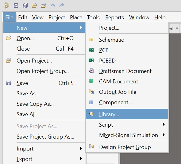
When you go through File > New > Library..., you create a new library file, which then opens in the Component Library Editor for editing. This is the beginning (start point) of the library editor.
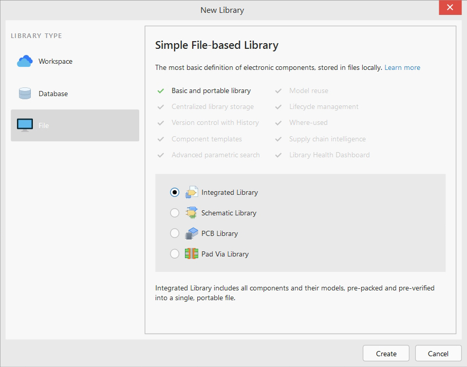
Integrated Library (.IntLib) This is a comprehensive library that combines both schematic symbols and PCB footprints of components in a single file. It contains complete information about a component - both how it appears on the schematic and how it should be placed on the printed circuit board. This is the most convenient format for distributing ready-made components, as everything necessary is contained in one file.
Schematic Library (.SchLib) This is a library of schematic symbols only. It contains graphical representations of components for circuit diagrams - how they look on the schematic, their pins, names, and electrical properties. It does not contain information about physical dimensions or placement on the printed circuit board. Used for drawing circuit diagrams.
PCB Library (.PcbLib) This is a library of footprints only (physical footprints) for printed circuit boards. It contains physical dimensions of components, contact pad layouts, package outlines, and soldering information. It does not contain schematic symbols. Used when routing printed circuit boards.
Pad Via Library (.PadViaLib) This is a specialized library of contact pads and vias. It contains various types and sizes of contact pads that can be used when creating footprints in PCB Library. These are basic elements for building more complex footprints.
Relationship between them:
Integrated Library = Schematic Library + PCB Library
Pad Via Library is used as "building blocks" for PCB Library
Creating a new library (Integrated Library, Schematic Library, PCB Library, Pad Via Library) means creating a new document/file that will be opened in the Editor for adding components, drawing symbols, creating footprints, setting up parameters.
Step 1: Create New Integrated Library
Go to File > New > Library > Integrated Library.
This creates a new .IntLib project that will contain all your components.
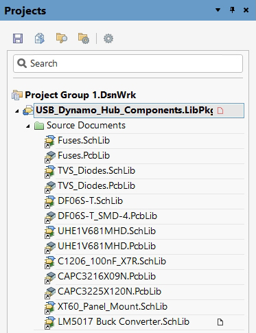
When you create a new Integrated Library project, you initially see "No Documents Added" status.

This means: The Integrated Library project (.LibPkg) has been created as a container, No actual library documents have been added to the project yet, The library is empty and cannot be compiled until documents are added.
Step 2: Add Schematic Library
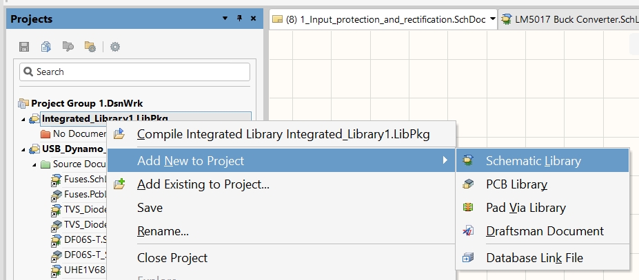
Right-click on the Integrated Library project in the Projects panel and select Add New to Project > Schematic Library. This creates a .SchLib file where you'll design schematic symbols.
Step 3: Add PCB Library
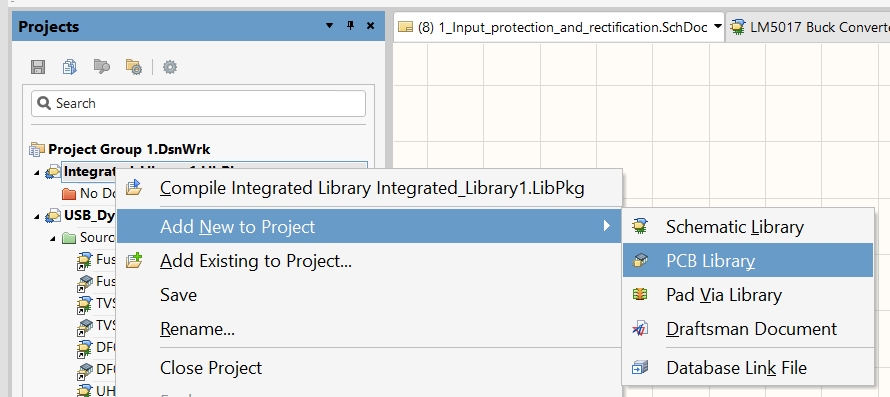
Similarly, right-click and select Add New to Project > PCB Library. This creates a .PcbLib file where you'll design footprints.
Step 4: Create Schematic Symbols
Open the Schematic Library (.SchLib) and create component symbols by: Drawing the component outline using lines and rectangles, Adding pins with proper electrical types (input, output, power, etc.), Setting component designator and comment fields, Defining component parameters and properties
Step 5: Create PCB Footprints
Open the PCB Library (.PcbLib) and create footprints by: Placing pads according to component datasheet specifications, Drawing component outline and courtyard, Adding silkscreen markings, Setting 3D body information if available
Step 6: Link Symbols to Footprints
In the Schematic Library, link each symbol to its corresponding footprint by setting the "Footprint" parameter to match the footprint name in the PCB Library.
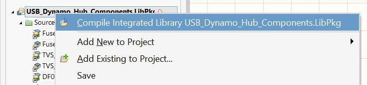
Step 7: Compile the Library
Right-click on the Integrated Library project and select "Compile Integrated Library". This combines all schematic symbols and footprints into a single .IntLib file.
Step 8: Validate and Test
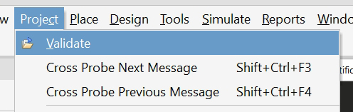
Check for compilation errors, test the library by placing components in a test project, and verify that all links between symbols and footprints work correctly. The result is a single .IntLib file containing complete, ready-to-use components with both schematic symbols and PCB footprints.
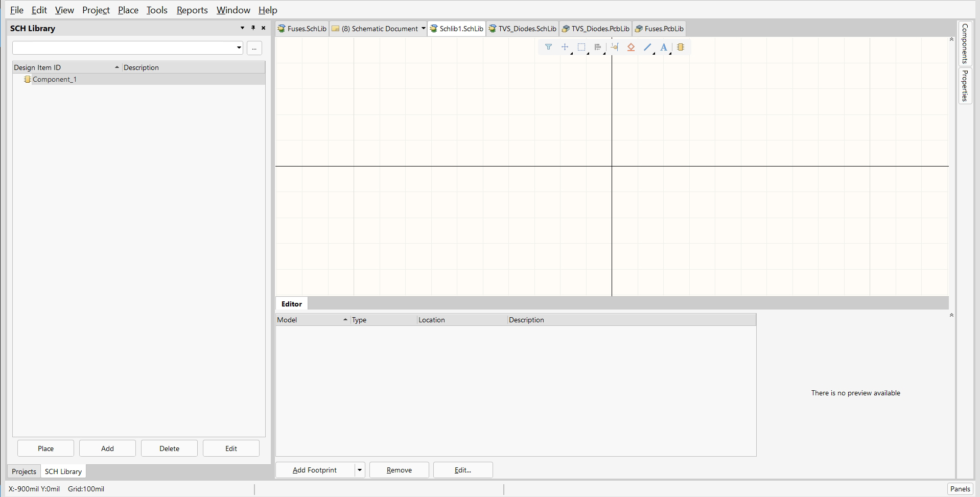
1. Library Panel (left side)
"SCH Library" - displays the list of components in the library
Design Item ID - unique component identifier (currently "Component_1")
Description - component description
Control buttons: Place, Add, Delete, Edit
2. Workspace (center)
Grid for drawing component symbols
Coordinate system (X=900mil Y=0mil Grid:100mil)
Here schematic symbols are drawn using lines, rectangles, circles, and pins
3. Properties Panel (right side)
"Components - Properties" - settings for selected component parameters
Here electrical and physical characteristics are defined
4. Models Panel (bottom)
"Editor" with columns: Model, Type, Location, Description
Shows linked models (3D models, SPICE models, simulation models)
Buttons: Add Footprint, Remove, Edit...
Symbol Creation:
Drawing geometric shapes (lines, rectangles, circles)
Adding pins with type configuration (Input, Output, Power, etc.)
Placing text (designator, comment, parameters)
Component Management:
Adding new components to the library
Editing existing symbols
Deleting components
Model Linking:
Adding footprints (Add Footprint)
Connecting 3D models
Configuring simulation models
This interface allows complete creation of a component schematic symbol with all necessary properties and models.
Create new schematic symbols in Schematic Library (.SchLib) files.
Editing of the seats in the PCB Library (.PcbLib) files.
Combine symbols, footprints, models, and parameters into a single component.
Use wizards, such as the Schematic Symbol Wizard or Footprint Wizard, to simplify creation.
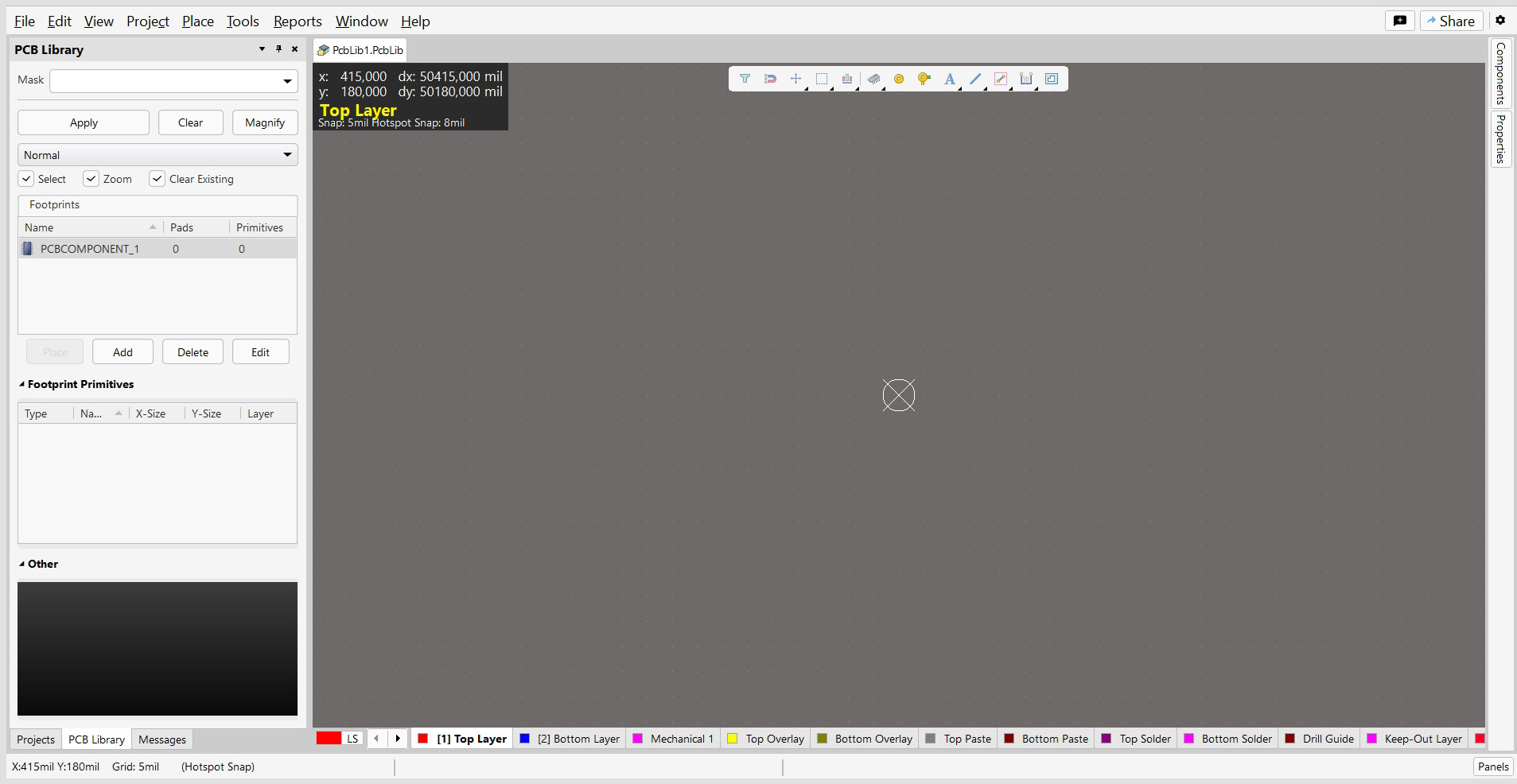
1. Control Panel (left side)
Mask Section: Dropdown menu with mask types for working with different elements, Apply, Clear, Magnify - buttons for applying, clearing, and magnifying.
Selection Tools: Normal - working mode, Select, Zoom, Clear Existing - selection and navigation tools
Footprints Management: Name, Pads, Primitives - columns with footprint information, PCBCOMPONENT_1 - current footprint (0 pads, 0 primitives), Add, Delete, Edit - footprint management buttons
2. Footprint Primitives:
Type, Name, X-Size, Y-Size, Layer - primitive properties
Here all footprint elements are displayed (contact pads, lines, text)
Black area - likely additional tools or preview
Workspace (center): Coordinate System:
X: 415,000 dx: 50415,000 mil
Y: 180,000 dy: 50180,000 mil
Top Layer active, with settings Snap: 5mil Footprint Snap: 8mil
Grid System:
Grid: 5mil with snap (Hotspot Snap)
Grid for precise element placement
Layer Panel (bottom):
Color indicators for different PCB layers:
LS (Layer Set)
Top Layer (red)
Bottom Layer (blue)
Mechanical 1 (pink)
Top Overlay, Bottom Overlay (yellow/green)
Top Paste, Bottom Paste (red)
Top Solder, Bottom Solder (purple)
Drill Guide (brown)
Keep-Out Layer (pink)
Functional Capabilities:
Footprint Creation:
Placing contact pads of different types and sizes
Drawing component outlines
Adding silkscreen markings
Setting up restriction areas (keepout)
Precise Positioning:
Coordinate snap with mil/mm accuracy
Different grid types for precision
Magnetic snap to reference points
Multi-layer Work:
Working with different PCB layers simultaneously
Visual representation of each layer with its own color
Ability to enable/disable layer visibility
This editor allows creating a complete footprint ready for PCB manufacturing with all necessary technological layers.
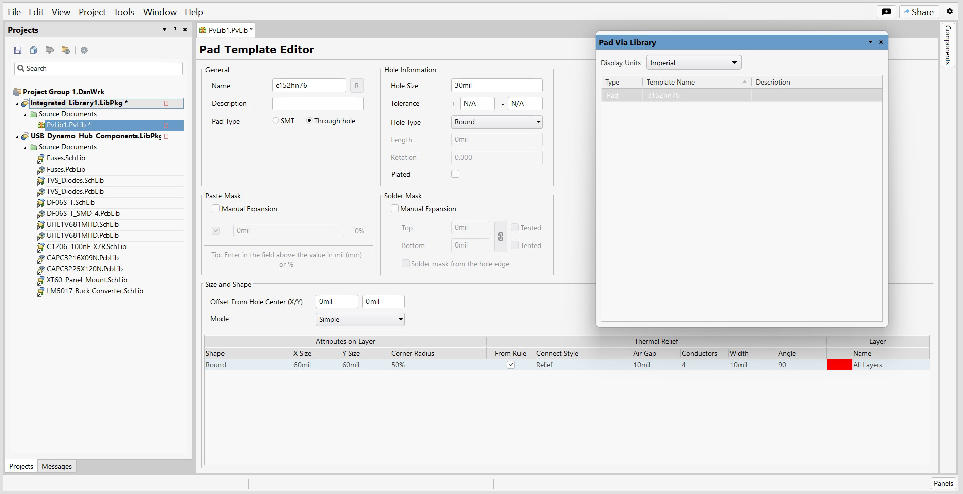
.1. General Section (basic parameters):
Name: c152n76 - pad template name
Description: field for describing the pad's purpose
Pad Type: choice between SMT (surface mount) and Through hole
2. Hole Information:
Hole Size: 30mil - hole diameter for through-hole components
Tolerance: N/A - allowable size deviations
Hole Type: Round - hole shape (round, oval, square)
Length, Rotation, Plated - additional hole parameters
3. Paste Mask (solder paste):
Manual Expansion: manual expansion settings
Fields for precise control of solder paste application
Tip: hint about entering values in mm or %
4. Solder Mask:
Manual Expansion: solder mask opening settings
Top/Bottom: 0mil - opening sizes for top/bottom
Tented - mask "tenting" option
Solder mask from the hole edge - mask from hole edge
5. Size and Shape:
Offset From Hole Center (X/Y): 0mil - offset from hole center
Mode: Simple - pad formation mode
6. Attributes on Layer: Table with settings for different layers:
Shape: Round - pad shape
X Size/Y Size: 60mil - pad dimensions
Corner Radius: 50% - corner rounding radius
7. Thermal Relief:
From Rule, Connect Style - connection rules to polygons
Air Gap, Conductors, Width, Angle - thermal relief parameters
Pad Via Library Panel (right side):
Display Units: Imperial - measurement units
Type, Template Name, Description - list of ready templates
Quick access to standard pad library
Practical Applications:
Creating Standardized Pads:
Developing typical pads for different packages
Setting up manufacturing technological parameters
Ensuring compliance with IPC standards
Soldering Quality Control:
Precise solder paste setup for optimal soldering
Heat dissipation management through thermal reliefs
Solder mask control for quality manufacturing
This editor ensures creation of professional, technologically correct contact pads considering all requirements of modern PCB manufacturing.
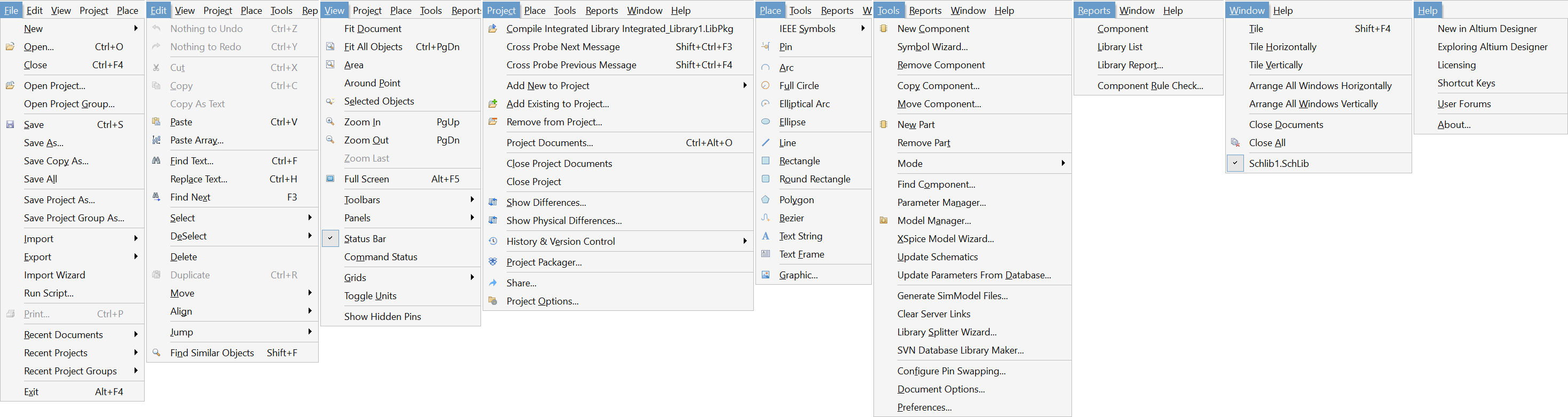
Looking at this menu structure, the unique items for Component Library Editor include:
New Component
Component Library List
Remove Component
Copy Component
Move Component
New Part
Remove Part
Find Component
Parameter Manager
Model Manager
XSpice Model Wizard
Update Schematics
Update Parameters From Database
Generate SimModel Files
Library Splitter Wizard
SVN Database Library Maker
Configure Pin Swapping
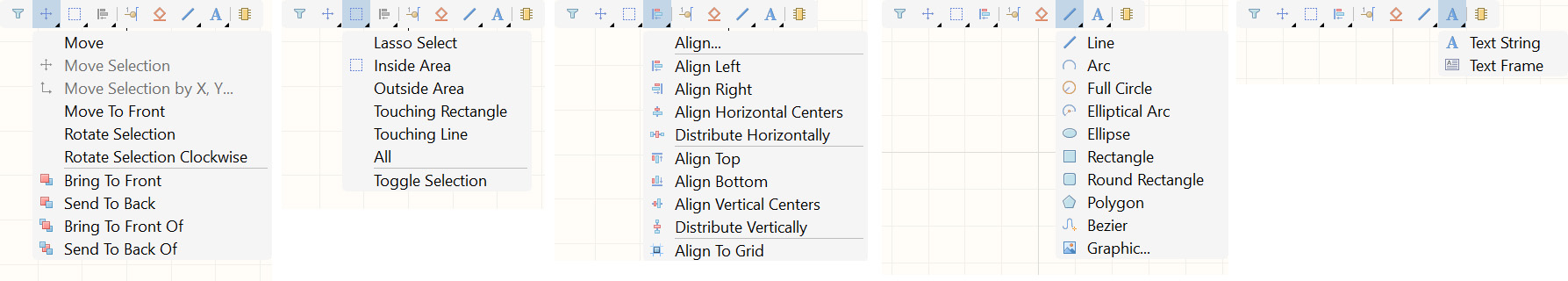
IEEE Symbols (with Pin submenu)
Pin
Text String
Text Frame
Various drawing primitives for component symbols (Arc, Full Circle, Elliptical Arc, Ellipse, Line, Rectangle, Round Rectangle, Polygon, Bezier)
In the Reports menu:
Component Library Report
Component Rule Check
In the File menu:
Compile Integrated Library
The panel allows to quickly change parameters without opening separate dialog boxes, which increases the efficiency of working with the component library.
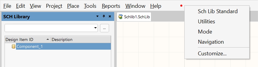
The Sch Lib Standard tab contains the standard properties for schematic libraries, including basic component parameters and display behavior settings.
The Utilities section offers auxiliary tools and utilities for library management, along with service functions for validation and verification tasks.
The Mode tab provides access to editor working modes, allowing you to configure the current editing mode and adjust tool behavior options.
Navigation settings control document navigation parameters, including zooming and panning controls, as well as grid and coordinate display options.
The Customize option enables interface personalization, toolbar configuration, and hotkey or menu setup. This Properties panel dynamically changes its content based on the selected tab, current tool, selected object in the editor, and working mode, providing contextual access to relevant settings without opening separate dialog windows.
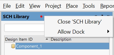
Close 'SCH Library' - close the schema library
Allow Dock - allow the panel to be docked
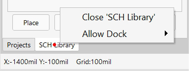
Close 'SCH Library' - close the schema library
Allow Dock - allow the panel to be docked
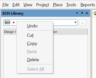
Undo - undo the action
Cut (Ctrl+X) - cut
Copy (Ctrl+C) - copy
Paste (Ctrl+V) - paste
Delete - delete
Select All - select all
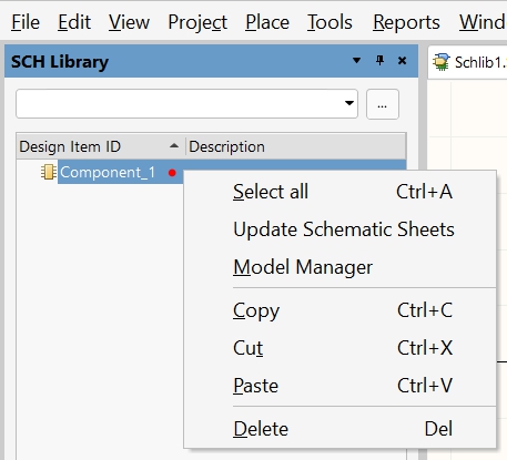
Select all (Ctrl+A) - select all
Update Schematic Sheets
Model Manager - model manager
Copy (Ctrl+C) - copy
Cut (Ctrl+X) - cut
Paste (Ctrl+V) - paste
Delete (Del) - delete
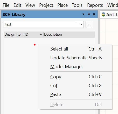
Select all (Ctrl+A) - select all
Update Schematic Sheets
Model Manager - model manager
Copy (Ctrl+C) - copy
Cut (Ctrl+X) - cut
Paste (Ctrl+V) - paste
Delete (Del) - delete
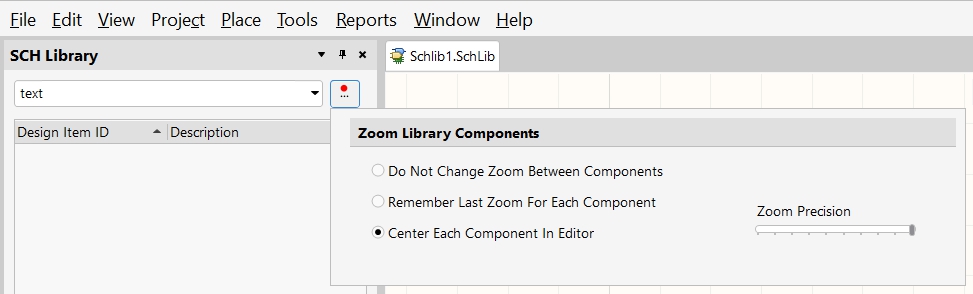
This is the Zoom Library Components dialog box or settings panel in the Schematic Library Editor. This dialog controls the zoom behavior when switching between different components in the library.
The dialog provides three zoom options: "Do Not Change Zoom Between Components" maintains the current zoom level when switching components, "Remember Last Zoom For Each Component" saves individual zoom settings for each component, and "Center Each Component In Editor" which is currently selected and automatically centers and fits each component in the editor view when selected.
On the right side, there's a "Zoom Precision" slider control that allows you to adjust the precision or sensitivity of the zoom functionality. This dialog helps customize how the editor handles component display and zoom behavior for better workflow efficiency when working with multiple components in a schematic library.
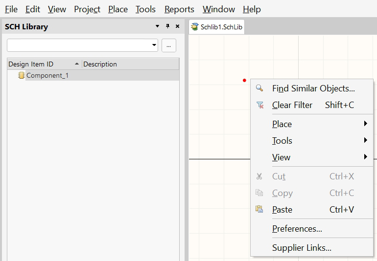
Find Similar Objects - find similar objects
Clear Filter (Shift+C) - clear the filter
Place - (Submenu: IEEE Symbols, Pin, Arc, Full Circle, Elliptical Arc, Ellipse, Line, Rectangle, Round Rectangle, Polygon, Bezier, Text String, Text Frame, Graphic)
Tools - tools (Submenu: New Component, Remove Component, First Component, Next Component, Previous Component, Last Component, New Part, Remove Part)
View - view (Submenu: Fit All Objects, Fit Document, Area, Around Point, Zoom in, Zoom Out, Zoom Last)
Cut (Ctrl+X) - cut
Copy (Ctrl+C) - copy
Paste (Ctrl+V) - paste
Preferences
Supplier Links - links to suppliers
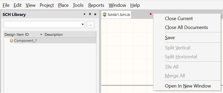
Close Current - close the current one
Close All Documents - close all documents
Save - save
Split Vertical - split vertically
Split Horizontal - split horizontally
Tile All - arrange in tiles
Merge All - merge everything
Open In New Window - open in a new window
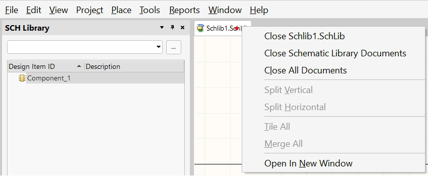
Close Schlib1.SchLib - close a specific library
Close Schematic Library Documents - close the schematic library documents
Close All Documents - close all documents
Split Vertical - split vertically
Split Horizontal - split horizontally
Tile All - arrange in tiles
Merge All
Open In New Window - open in a new window
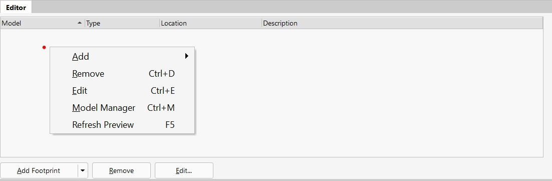
Add - add (Submenu: Footprint, Pin Info, PCB3D, Simulation, Ibis Model, Signal Integrity)
Remove (Ctrl+D) - delete
Edit (Ctrl+E) - edit
Model Manager (Ctrl+M) - model manager
Refresh Preview (F5) - refresh the preview